Elaine F. Houston1,2, Lakeishia Brown3, Joshua Barbara4, Garrett Grindle1,2, Hongwu Wang1,2, Annmarie Kelleher1,2, Mark Schmeler1,2, and Rory A. Cooper1,2
1Human Engineering Research Laboratories, Department of Veterans Affairs, Pittsburgh, Pennsylvania; 2Department of Rehabilitation Science and Technology, University of Pittsburgh, Pittsburgh, Pennsylvania; 3Rochester Institute of Technology, Rochester, New York; 4Penn State Behrend, Erie, Pennsylvania
Abstract
In the United States approximately 150,000 people with disabilities could benefit from the use of an assistive robotic manipulator. These assistive robots can help to perform basic and instrumental activities of daily living. One of the challenges of being able to study these technologies is the evaluation and comparison of assistive robot performance. A standardized protocol is necessary to allow for researchers and clinicians to test different assistive technologies and robotics.
To meet this need, a modular activities of daily living task board has been developed to measure task performance. Vertical and horizontal boards were developed to include a wide range of activities of daily living along with the sensors needed to detect the activities.
Keywords
Activities of Daily Living, Assistive Technology, Robotics, Task Performance, Functional Assessment, Outcome Measures.Background
In the United States today, many people with disabilities are not able to complete basic real world tasks without the help of a caregiver. Approximately 150,000 people in the United States could benefit from the use of an assistive robotic manipulator [1]. Washing the dishes, flipping a light switch, and pushing an elevator button are all examples of simple things that may require the assistance of a manipulator.
Over the past 50 years, 12 different assistive robotic manipulators, in addition to other assistive robots, have been developed and evaluated [2]. These include both wheelchair mounted robotic manipulators (WMRM) as well as robots built into the environment or integrated into larger mobile systems. Examples of WMRM include the Manus ARM and the newer iARM developed by Exact Dynamics (Dindom, The Netherlands), and the JACO and MICO manipulators developed by Kinova Robotics (Montreal, Canada). These WMRM are frequently controlled via computer input devices including joysticks, keypads, or touchscreens. The Personal Mobility and Manipulation Appliance (PerMMA) is a wheelchair that integrates bimanual manipulation with two Manus ARMs on a carriage and track mounting system to enhance its manipulability and mobility [3,4]. The Home Exploring Robotic Butler 2.0 (HERB), designed to perform useful tasks in the human environment, integrates two 7DOF WAM Arms with BarrettHands on a mobile Segway base [5].
One of the challenges our research team faced was how to evaluate and compare performance using these assistive robots. In a 2013 literature review by Chung, the current state of functional assessment and performance evaluations for assistive robotic manipulators was analyzed. In this article he concluded there is a need for standardized activities of daily living (ADL) for measuring task efficiency and performance of assistive robotic manipulators [2]. Additionally, while many standardized occupational therapy hand function and task performance tests are available, none are ideally suited for testing robotic manipulators.
Currently only one Activities of Daily Living Task Board was created to meet this need [6]. This board as described by Chung includes 6 electronic tasks including a large circular button (door opener), a small circular button (elevator button), a rectangular shaped rocker light switch, a toggle switch, a lever style door handle, and a knob. These tasks were integrated into a small, compact panel connected to a data acquisition system running on a laptop computer via an Arduino toolkit. Task completion times were measured from the time the robot left the start button in front of the board until a task switch was activated or a preset angle was reached while turning the knob or door handle. However, this board is limited in the range and scope of tasks that can be tested. In addition, the tasks represented in the board only cover a small range of the manipulation capability required to complete ADL.
Objective
A new ADL task board was needed to meet the need for a comprehensive functional and performance assessment tool to be used in evaluating assistive robotic manipulators. The objective of this project was to develop a modular ADL task board to quantify and standardize the measurement of task performance.
Approach
To meet the objective, a modular ADL task board was designed so that a large number of tasks could be tested and the location of the tasks on the board could be changed as needed to simulate a wide range of ADL in the environment. The goal was to create a task board that included everyday ADL in a range of positions with both a vertical and horizontal orientation. It was important that the tasks were contained in their own modules so their positions or orientation could be easily changed or switched with another module to change the task being tested. The initial range of tasks to be included was based on conversations with several assistive robotics researchers and occupational therapists. A vertical as well as a horizontal support structure was created to allow for module placement in the proper orientation for the given task as it would be commonly found. A standardized set of mechanical and electrical connections was used to allow any module to be supported in any slot on the support structure. The standardized electrical connections allowed for the interfacing of the task to a data acquisition system allowing for the automatic measurement of task completion time as well as the current status of a task including on/off of a switch or rotational position of a knob. Additionally, appropriate feedback such as the completion or status of a task could be given on any module.
Mechanical Support Structure
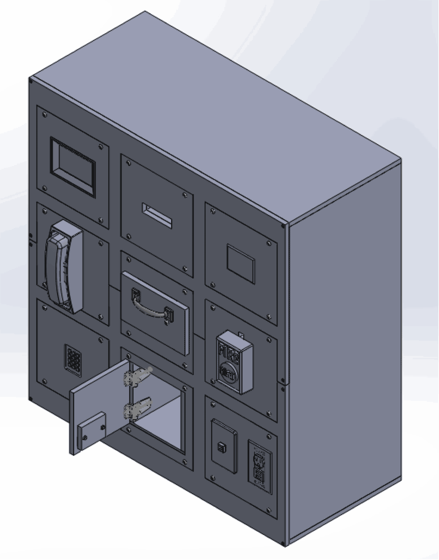 Figure 1: Front of Modular ADL Board with 9 tasks shown
 Two different mechanical support structures, a vertical and a horizontal configuration, were developed for the initial configuration of the modular ADL board. Each configuration was designed to be constructed from half inch plywood so it would be sufficiently strong and visually appealing while still remaining economical. The first configuration consisted of a three by three matrix of stacked slots to accommodate a total of nine modules at any one given point. The overall size of this configuration was approximately 3ft by 3ft by 15in deep. The second configuration supported three modules placed side-by-side and measured approximately 3ft x 14in x 7in overall.
Each slot allowed for flush mounting of any module into the support structure. Four barbed, threaded inserts were used to fasten a module to the board while still allowing for the modules to be repeatedly removed from the board without damaging it.
Modules
The individual modules were designed to house one or more individual tasks on a single 9in by 9in board. Standards were maintained to allow for any module to be mounted to the support structure despite individual module configurations as well as any required sensing hardware. Each module also contained a custom printed circuit board (PCB) with the required specialized circuitry to interface with the sensors necessary to record the task, including potentiometers, momentary switches and other integrated interfaces.
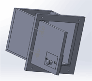 Figure 2: Cabinet Module including a door with interchangeable knob
Opening and closing a drawer or cabinet are both important daily tasks that are frequently used. Therefore, special modules were created to test these activities. A method was needed to switch between the various types of cabinet and drawer pulls and handles. This was accomplished by adding another panel inside the front panel of the cabinet or drawer. Each individual handle is attached to its own small board that fits flush into an opening on the front panel, so that it can be mounted flush to the front of the cabinet or drawer, as seen in figure 2.
Examples of tasks integrated into the current modules include a range of light and dimmer switches, electrical outlets, a touchscreen, a keypad, fire alarms, push-pull and swipe credit card readers, a coin slot, faucets, and a toilet tank lever.
Electrical System
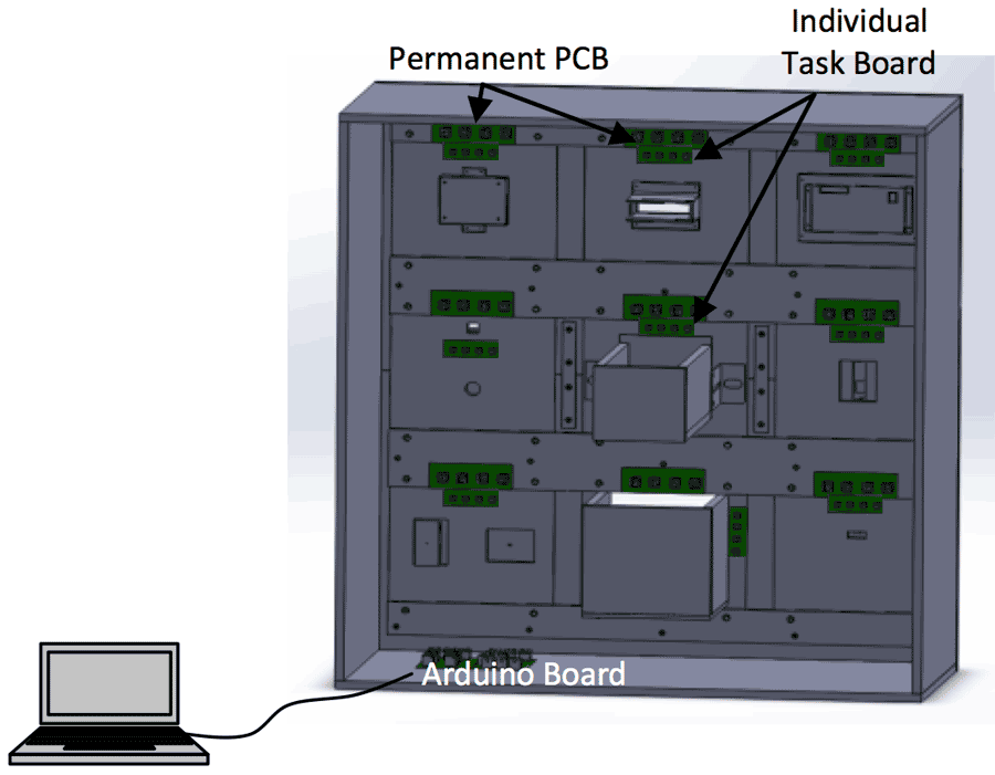 Figure 3: Electrical configuration of ADL board
A modularized electrical system was required to measure the task completion time and to provide feedback from each module to the user. The overall setup (Figure 3 and Figure 4) included a computer to run the user interface, which connected via USB to an Arduino Mega ADK board. This board collected data from nine connected, permanently mounted PCBs. These nine PCBs were mounted to the top of each module slot inside the support structure. PCBs located on each task board connected to the permanently mounted PCBs via RJ45 (Ethernet) ports and CAT5 cables.
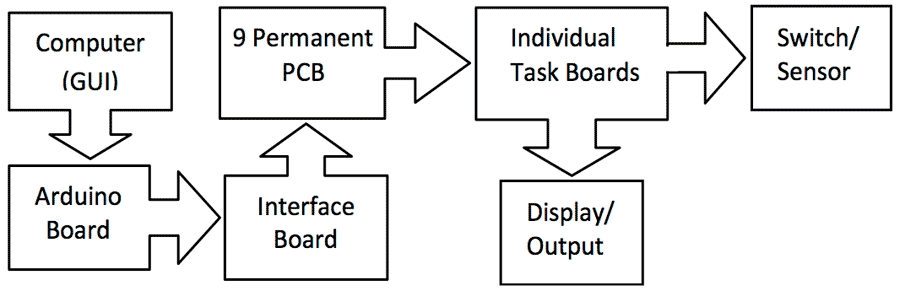 Figure 4: Flowchart of connection between components
Each module was provided with three digital lines, one pulse width modulation line, one analog line, one communication, and two multiplexer control lines, as well as a 5 volt power line and a grounding line. These connections allowed for the support of a wide range of sensor inputs and feedback and control outputs necessary to allow for the testing of a wide range of tasks. For example, the fire alarm test module detected the activation of the switch, and signaled the task completion to the computer which triggered a buzzer to signify the completion of the task. Similarly, a test module representing an oven knob used a potentiometer to track the movement of the knob, and signaled this action to the computer which displayed the simulated temperature on a seven segment display.
Procedure for Use
The process to use the board to test an assistive robotic manipulator was straightforward. After the desired modules and their locations were selected, they could be inserted into the desired slot and secured using 4 button head screws. The two CAT5 cables could then be connected between the permanently mounted PCB and the individual task boards. The USB cable between the computer and the ADL Task board could be connected and the power turned on. In the graphical user interface, the desired task was selected. To begin that task, the robot manipulator was moved into position to depress the start button located in front of the modular ADL task board. Time started when the assistive robotic manipulator released the start button and ended when the desired task was completed with feedback provided.
Future work
To make these modular ADL task boards a viable system, focus groups with assistive robotics researchers, clinicians, and end-users are needed to further define the range of tasks that should be implemented and included as modules for the modular ADL task board. Also, studies need to be completed with a range of populations to validate this as a tool and establish normative values for these tasks using a range of assistive technologies.
IMplications
The adoption of this new modular ADL task board would allow for a standardized approach to testing the performance of assistive robotic manipulators in the context of subtasks required to complete ADL. This task board could be used in research settings to evaluate not just the performance of robotic manipulators, interfaces, and their users, but also for clinical applications such as upper extremity prosthetics, and the rehabilitation of individuals with upper extremity impairments.References
[1] Laffont, I., Biard, N., Chalubert, G., Delahoche, L., Marhic, B., Boyer, F. C., et al. (2009). Evaluation of a Graphic Interface to Control A Robotic Grasping Arm: A Multicenter Study. Arch Phys Med Rehabil, 90, 1740-1748
[2] Chung, C.-S., Wang, H., & Cooper, R. A. (2013). Functional assessment and performance evaluation for assistive robotic manipulators: Literature review. The Journal of Spinal Cord Medicine, 36(4), 273-289.
[3] Wang H, Xu J, Kelleher AR, Ding D, Grindle GG, Vazquez J, Salatin B, Cooper RA,Performance Evaluation of the Personal Mobility and Manipulation Appliance(PerMMA), Medical Engineering and Physics, pp. 1613-1619, Vol. 35, No. 11, November 2013.
[4]Cooper RA, Grindle GG, Vazquez JJ, Xu J, Wang H, Candiotti J, Salatin B, Houston E, Kelleher AR, Cooper RM, Teodorski E, Beach S, Personal Mobility and Manipulation Appliance - Design, Development and Initial Testing, Proceedings of the IEEE, pp. 2505-2511, Vol. 100, No. 8, August 2012.
[5] Srinivasa, S. S., Berenson, D., Cakmak, M., Collet, A., Dogar, M. R., Dragan, A. D. et al. (2012). HERB 2.0: Lessons Learned from Developing a Mobile Manipulator for the Home. Proc IEEE, 100(8), 1-17.
[6]Chung C, Wang H, Kelleher AR, Cooper RA, Development of a Standardized Performance Evaluation ADL Task Board for Assistive Robotic Manipulators, Proceedings of the Rehabilitation Engineering and Assistive Technology Society of North America Conference, Seattle, WA, June 20-24, 2013.
Acknowledgements
This work was supported in part by The Quality of Life Technology-Engineering Research Center, NSF, grant # EEC0540865; IGERT: Interdisciplinary Research Training in Rehabilitation Engineering, NSF, grant # 1144584; American Student Placements in Rehabilitation Engineering, NSF, grant # 1262670; and Research Experience for Undergraduates (REU) in Quality of Life Technology (QoLT), NSF, grant # 0540866. Any opinions, findings, and conclusions or recommendations expressed in this material are those of the authors and do not necessarily reflect the views of the NSF and Department of Veterans Affairs.
Audio Version PDF Version